- 您现在的位置:买卖IC网 > Sheet目录1214 > EVAL-ADE7758ZEB (Analog Devices Inc)BOARD EVAL FOR AD7758
�� �
�
�PRELIMINARY� TECHNICAL� DATA�
�EVAL-ADE7758EB�
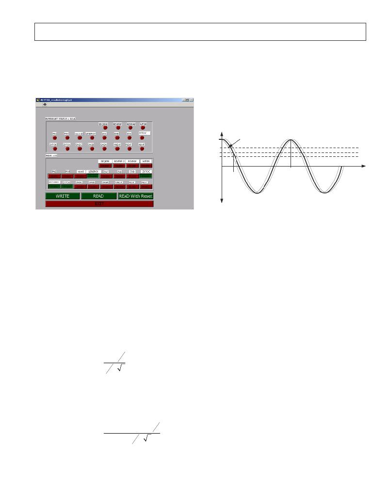
�Interrupts�
�This� window� gives� access� to� the� Interrupt� Mask� and� STA-�
�TUS� registers� of� the� ADE7758� -� see� Figure� 14� .� For� details�
�on� how� to� use� the� Interrupt� and� Mask� registers,� refer� to� the�
�ADE7758� datasheet.�
�the� phase� difference� at� the� input� to� the� Current� channel� is� now�
�59.89°� lag� instead� of� 60°� lag.� Determining� whether� the� error�
�is� a� lead� or� lag� can� also� be� figured� intuitively� from� the�
�frequency� output.� Figure� 14� shows� how� the� output� frequency�
�varies� with� phase� (cos{� φ� }).� Since� the� output� frequency� B�
�(1.83817Hz)� at� the� PF=0.5� lag� setting� in� the� example� is�
�actually� greater� than� A/2� (1.833105Hz),� this� means� the� phase�
�error� between� the� current� channel� and� the� voltage� channel�
�was� actually� less� than� 60°.� This� means� there� was� additional�
�lead� in� the� current� channel� due� to� the� CT.�
�CF� (Hz)�
�Frequency� B� >� A/2�
�PF=1�
�Phase� difference� <� 60� lag�
�PF>0.5�
�PF=0.5�
�PF<0.5�
�PF=0�
�360�
�60�
�Phase� lag�
�Figure� 14—CF� Frequency� Vs� Phase(PF)�
�Phase� Error� (� °� )� =� Tan� ?� 1� ?�
�?� ?� A� ?� 3� ?� ?�
�Phase� Error� (� )� =� Tan� ?� 1� ?�
�?� ?�
�?� ?�
�3� .� 66621� ?� 3�
�Figure 14 - Interrupts Window�
�Measuring� CT� Phase� Errors� using� the� ADE7758�
�The� ADE7758� itself� can� be� used� to� measure� a� CT� (and�
�external� components)� phase� error� during� calibration.� The�
�assumption� is� that� the� ADE7758� has� no� internal� phase� error�
�(APHCAL� =� BPHCAL� =� CPHCAL� =� 00� hex)� and� the� error�
�due� to� external� components� is� small� (<0.5°).� The� procedure�
�is� based� on� a� two� point� measurement,� at� PF=1� and� PF� =� 0.5�
�(lag).� The� PF� is� set� up� using� the� test� bench� source� and� this�
�source� must� be� very� accurate.� The� ADE7758� should� be�
�configured� for� Active� Energy� measurement� mode.�
�An� Active� Energy� measurement� is� first� made� with� PF=1�
�(measurement� A).� A� second� Active� Energy� measurement�
�should� be� made� at� PF=0.5� (measurement� B).� The� frequency�
�output� CF� can� be� used� for� this� measurement.� Using� the�
�formula� shown� below� the� phase� error� is� easily� calculated:�
�?� B� ?� A� ?�
�2� ?�
�2�
�For� example,� using� the� frequency� output� CF� to� measure�
�power,� a� frequency� of� 3.66621Hz� is� recorded� for� a� PF=1.�
�The� PF� is� then� set� to� 0.5� lag� and� a� measurement� of�
�1.83817Hz� is� obtained.� Using� the� formula� above� the� phase�
�error� on� Channel� 1� is� calculated� as:�
�?� 1� .� 83817� ?� 3� .� 66621� ?�
�°� 2� ?� =� +� 0� .� 0� 9� 1� °�
�2�
�The� formula� will� also� give� the� correct� sign� for� the� phase�
�error.� In� this� example� the� phase� error� is� calculated� as� +0.091°�
�at� the� input� to� the� Current� channel� of� ADE7758.� This� means�
�that� the� CT� has� introduced� a� phase� lead� of� 0.091°.� Therefore�
�REV.� PrB� 08/03� –9–�
�Using� the� Phase� Calibration� to� correct� small� (<0.5°)�
�external� phase� errors�
�From� the� previous� example� it� is� seen� that� the� CT� introduced�
�a� phase� lead� in� the� current� channel� of� 0.091°� .� Therefore�
�instead� of� 60°� phase� difference� between� the� current� channel�
�and� the� voltage� channel,� it� is� actually� 59.89°.� In� order� to�
�bring� the� phase� difference� back� to� 60°,� the� phase� compensa-�
�tion� circuit� in� the� voltage� channel� is� used� to� introduce� an�
�extra� lead� of� 0.091°.� This� is� achieved� by� reducing� the� amount�
�of� time� delay� in� the� voltage� channel.�
�The� maximum� time� delay� adjustment� in� the� voltage� channel�
�is� ±75.6μs� with� a� CLKIN� of� 10MHz.� The� PHCAL� registers�
�are� signed� 2's� complement� 7� bit� registers.� Each� LSB� is�
�equivalent� to� 1.2μs.� In� this� example� the� line� frequency� is�
�50Hz.� This� means� each� LSB� is� equivalent� to� (360°� x� 1.2μs�
�x� 50)� =� 0.022°.� To� introduce� a� lead� of� 0.091°� the� delay� in� the�
�voltage� channel� must� be� reduced.� This� is� achieved� by� writing�
�-4� (1Ch)� or� +0.088°� to� the� PHCAL� register.�
�Correcting� large� external� phase� errors�
�In� this� example� the� phase� correction� range� at� 50Hz� is� only�
�approximately� ±1.3°.� However� it� is� best� to� only� use� the�
�PHCAL� register� for� small� phase� corrections,� i.e.,� <0.5°.� If�
�larger� corrections� are� required� the� larger� part� of� the� correc-�
�tion� can� be� made� using� external� passive� component.� For�
�example� the� resistors� in� the� anti-alias� filter� can� be� modified�
�to� shift� the� corner� frequency� of� the� filter� so� as� to� introduce�
�more� or� less� lag.� The� lag� through� the� anti-alias� filters� with�
�1k� ?� and� 33nF� is� 0.56°� at� 50Hz.� Fine� adjustments� can� be�
�made� with� the� PHCAL� register.� Note� that� typically� CT� phase�
�shift� will� not� vary� significantly� from� part� to� part.� If� a� CT�
�phase� shift� is� 1°,� then� the� part� to� part� variation� should� only� be�
�about� ±0.1°.� Therefore� the� bulk� of� the� phase� shift� (1°)� can� be�
�canceled� with� fixed� component� values� at� design.� The� remain-�
�ing� small� adjustments� can� be� made� in� production� using� the�
�PHCAL� registers.�
�发布紧急采购,3分钟左右您将得到回复。
相关PDF资料
EVAL-ADE7759EBZ
BOARD EVALUATION FOR ADE7759
EVAL-ADE7762EBZ
BOARD EVALUATION FOR ADE7762
EVAL-ADE7763ZEB
BOARD EVALUATION FOR ADE7763
EVAL-ADE7816EBZ
BOARD EVALUATION FOR ADE7816
EVAL-ADE7878EBZ
BOARD EVAL FOR ADE7878
EVAL-ADE7880EBZ
BOARD EVAL FOR ADE7880
EVAL-ADE7953EBZ
BOARD EVAL FOR ADE7953
EVAL-ADF4002EBZ1
BOARD EVAL FOR ADF4002
相关代理商/技术参数
EVAL-ADE7759E
制造商:AD 制造商全称:Analog Devices 功能描述:Active Energy Metering IC with di/dt Sensor Interface
EVAL-ADE7759EB
制造商:Analog Devices 功能描述:Power Metering, Active Energy Metering IC with di/dt Sensor Interface 制造商:Analog Devices 功能描述:EVAL FOR EN METER IC W DI/DT SENS INTRFC - Bulk
EVAL-ADE7759EBZ
功能描述:BOARD EVALUATION FOR ADE7759 RoHS:是 类别:编程器,开发系统 >> 评估演示板和套件 系列:- 标准包装:1 系列:- 主要目的:电信,线路接口单元(LIU) 嵌入式:- 已用 IC / 零件:IDT82V2081 主要属性:T1/J1/E1 LIU 次要属性:- 已供物品:板,电源,线缆,CD 其它名称:82EBV2081
EVAL-ADE7762EBZ
功能描述:BOARD EVALUATION FOR ADE7762 RoHS:是 类别:编程器,开发系统 >> 评估演示板和套件 系列:- 标准包装:1 系列:- 主要目的:电信,线路接口单元(LIU) 嵌入式:- 已用 IC / 零件:IDT82V2081 主要属性:T1/J1/E1 LIU 次要属性:- 已供物品:板,电源,线缆,CD 其它名称:82EBV2081
EVAL-ADE7763EB
制造商:Analog Devices 功能描述:EVALUATION BOARD DOCUMENTATION ADE7763 ENERGY METERING IC
EVAL-ADE7763ZEB
功能描述:BOARD EVALUATION FOR ADE7763 RoHS:是 类别:编程器,开发系统 >> 评估演示板和套件 系列:- 标准包装:1 系列:PSoC® 主要目的:电源管理,热管理 嵌入式:- 已用 IC / 零件:- 主要属性:- 次要属性:- 已供物品:板,CD,电源
EVAL-ADE7816EBZ
功能描述:BOARD EVALUATION FOR ADE7816 RoHS:是 类别:编程器,开发系统 >> 评估演示板和套件 系列:- 标准包装:1 系列:PSoC® 主要目的:电源管理,热管理 嵌入式:- 已用 IC / 零件:- 主要属性:- 次要属性:- 已供物品:板,CD,电源
EVAL-ADE7854EBZ
制造商:Analog Devices 功能描述:EVALUATION BOARDS - Boxed Product (Development Kits)